Modeling Class Hierarchies
When programs get more complex more support is needed in desiging them. It is even more important to be able to se the program structure and behaviour as parts and as a whole. Unified Modelling Language (UML) is a standardized modelling language for object oriented design. UML is probably the notation most used for depicting programs durign program design so it is worth to know its core features. In practice however, it is quite common to use free form ways to depict program structure. Typically these also are heavily influenced by the core diagram types of UML. Having understanding on the general principles behind program behaviour modelling also makes doodling easier. It is also good to keep in mind that UML or any other model does not take a stanse on what a good program structure or interface is. They only provide a way to depict program structure and runtime behaviour in a way everybody can understand.
The diagram types provided by UML can be divided into two basic types: structural and behavioral diagrams. The structure diagnrams represent the basic program structure that do not change (are static) i.e. relationships between classes, interfaces and objects. Behavioral diagrams in trun represent the runtime (dynamic) behaviour of the program.
Structure Diagrams
In UML classes, objects instantiated from them and interfaces are represented by boxes.
Inside the box the attributes, services in the public interface and an explanation on the responsibilities of the class are given, each in a slot of their own
An object is represented similarluy but an identity (a name) is given for it at the top of the box in addition to the class of the object.
Attributes can also be given values.
A word <<interface>> is added to the box when a functional unit needs to be represented purley as a public interface.
An abstract base class and the methods of its interface the class does not implement can be marked with {abstract}.
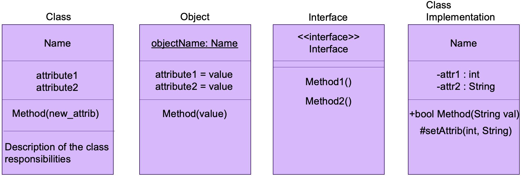
CLass, Object, Interface and Class Implementation in UML
Implementation details should not be at focus when starting with program design UML makes it possible to represent access modifiers as a part of the class structure.
Visibility |
Notation |
|---|---|
|
|
|
# |
|
|
|
~ |
The connections between classes must also be shown in the class diagram. This is done by marking associations between classes in lines and arrows representing the type of the connection.
Dependency: a one way connection that only telss that a class (A) depends on another class (B). Class A needing class B for something in its behaviour is marked with as a dashed line with an open arrow that points from A to B.
Association: represents different types of links between classes. The simplest association if a line between classes. Different kinds of information on the type of connection is often added to the association (textual or numeric information). In a unidirectional association only one of the classes is aware of the association. Association can also be a composition or aggregation.
Composition: a composition is represented as a filled diamond shape and in it the lifetimes of the objects are tightly connected to eachother. When an object is deleted also the object it is composed of get deleted.
Aggregation: an aggregation is represented with a hollow diamond shape. Aggregation differs from composition in that in aggregation object lifetimes are not as tightly tied to each other: a deleted object doesn’t necessarily delete its aggregate objects.
Inheritance: inheritance is represented with a hollow triangle on the end of the base class.
Realization/Implementation: implementing an interface is represented with a hollow triangle on a dashed line at the end of the interface. A line form where the box of the interface is replaced by the name of the interface and the triangle with a small circle can also be used.
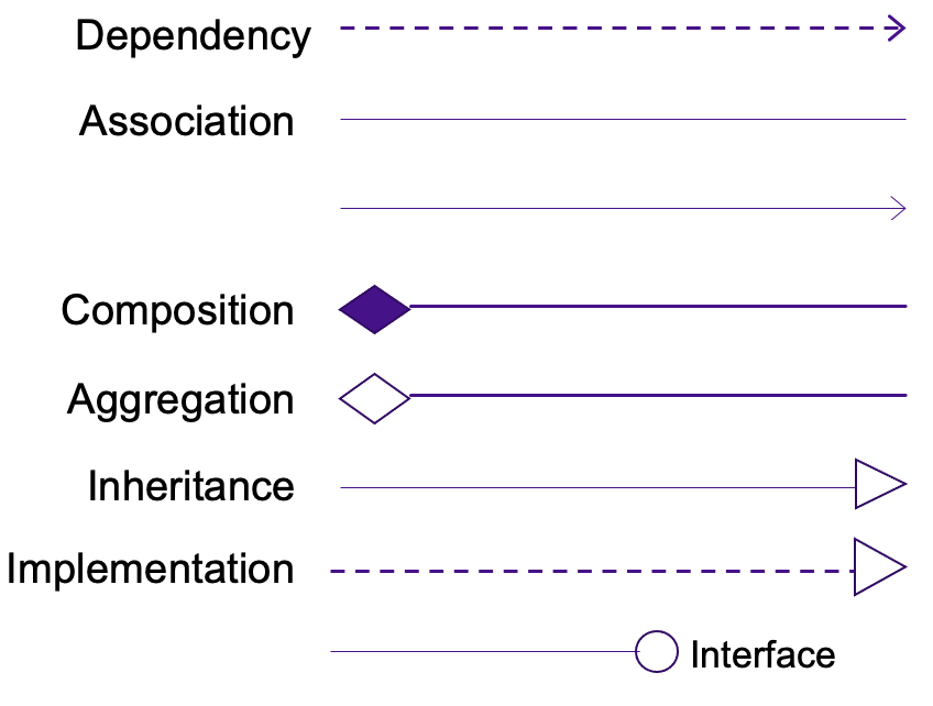
UML representations of connection types.
Representing Behaviour
A sequence diagram is one diagram that can be usedd to represent the execution of the program. Other include use cases and the state diagram. A use case diagram represents the ways the user can interact with the program. In therm the user (an actor) is often depicted as a stick figure and the use cases as ovals or circles. A sequence diagram shows how the object in the programn call the services of each of the objects. Vertical lines represent the interfaces of the objects and fthe function calls between objects are marked with arrows. Time runs top down in a sequence diagram.
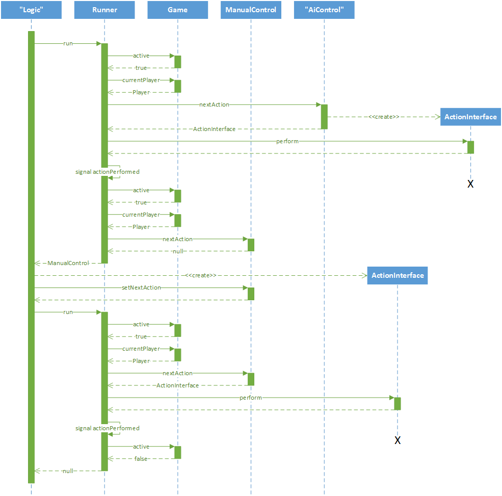
An example of a sequence diagram of a card game
A state diagram can be used to represent functional states and changes from state to state. Execution always starts from an initial state represented with a black full circle and ends in one or more final states represented with black filled circles with a circle around it.