Network protocols and their security
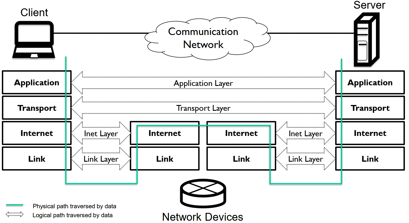
The entirety of data communication forms a complex system. Understanding distributed applications, network technologies, and data communication connections is facilitated by the layered model. The figure shows the 4-layer TCP/IP stack, which is named after the protocols of its transport and internet layers, TCP and IP. There are three devices shown: a client machine, a router, and a server, as well as the physical and logical paths of data between the parties. Multiple network protocols may operate at different layers. Some are general, while others are tailored to specific network architectures. A protocol is a set of rules, that is, a standard that defines how data communication between different layers is handled.
In this section, network security is examined layer by layer from top to bottom. The next section complements this with specific security mechanisms.
Application layer security
This subsection examines the protection of email and web browsing. In addition to the protocols presented here, important “utility” protocols at the application level that require protection include NTP and DNS, Network Time Protocol and Domain Name System.
Email (S/MIME) and messaging security
MIME defines a way to transmit email messages using different character sets and to include images or other documents as attachments. Secure MIME, or S/MIME, specifies how email messages and signatures are packaged into emails according to the MIME standard. S/MIME defines encryption and signing of emails using public-key cryptography. It provides confidentiality, authenticity, and integrity for messages. For two users to reliably exchange messages according to the S/MIME standard, both must have a certificate signed by a trusted authority. In most cases, there are no separate S/MIME applications; instead, different programs include their own built-in S/MIME implementations, often without explicitly mentioning the abbreviation “S/MIME”.
HTTPS
HTTPS, that is, HTTP over TLS (RFC2818), provides a secure connection between communicating parties in the WWW environment, using the TLS protocol for authentication and encryption (or the now outdated but almost similar SSL protocol). TLS is discussed below, “half a layer lower”. In a browser, the protocol in use is HTTPS when the address begins with ”https://”. Normally, HTTPS uses TCP port number 443.
Anonymous and censorship-resistant communication (advanced)
Anonymous communication is a dual phenomenon: it supports freedom of expression but makes it more difficult to ensure accountability of the parties. It can be used, for example, in situations where one wishes to communicate against oppressive regimes without fear of consequences.
Anonymity can be increased by distributing data transmission and routing it through multiple networks. This approach is represented by anonymous communication networks, the most well-known of which is Tor. The name originally comes from The Onion Router, and the onion metaphor describes layered encryption. In Tor, traffic passes through multiple (typically three) intermediate nodes in layers of encryption. The client selects an entry node, one or more middle nodes, and an exit node, and constructs the message for these nodes but sends it only to the entry node. The nodes form a so-called circuit through which all communication flows in both directions. On the forward path, each node decrypts only its own layer and learns the next node, helping to preserve the sender’s anonymity. Correspondingly, on the return path, nodes add layers of encryption.
Between the application and transport layers
In fact, TLS, Transport Layer Security, belongs to the transport layer according to its name, but it is most naturally considered as its own intermediate layer, also associated with the public key infrastructure (PKI) system.
TLS
The following describes the basic implementation of the TLS protocol, complementing the presentation found in the applied cryptography module.
Among the newest and most widely used TLS versions, 1.2 and 1.3 focus particularly on the handshake process, which represents functionality characteristic of the application layer. Details include authentication of communicating parties, agreement on encryption algorithms to be used, required key operations, and key exchange mechanisms.
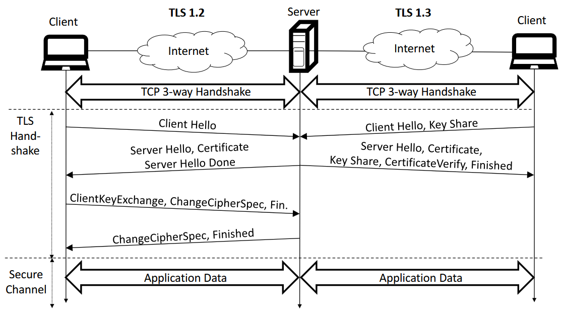
Handshake: TLS 1.2 on the left and TLS 1.3 on the right. Optional client authentication is omitted.
Let us first examine the handshake in TLS version 1.2. The client and server negotiate which TLS version, encryption algorithms, cryptographic methods, etc. they will use. Certificates are exchanged for mutual authentication, although client authentication is optional and not shown in the figure. Next, a shared symmetric key is established. The client may encrypt a generated symmetric key using the server’s public key (e.g. RSA), and the server decrypts it using its private key. Alternatively, the parties can jointly generate a key using the Diffie-Hellman-Merkle key exchange (DHKE). DHKE provides TLS with forward secrecy. It prevents attackers from decrypting past communications even if the server’s private key is later compromised. Finally, the handshake ensures the integrity of the communication session. From this point onward, during the data transfer phase, TLS peers use the established keys to encrypt and authenticate subsequent communication.
In TLS 1.3, the handshake process has been made more efficient. The number of round trips has been reduced to one without compromising security. TLS 1.3 no longer supports RSA-based key exchange as an alternative to DHKE. Therefore, the client “guesses” the chosen key exchange protocol (e.g. DHKE) and sends its key share already in the initial step. The server responds with selected parameters defining the protocols, keys, certificate, and signature used in the handshake (in the CertificateVerify message). If the client has previously connected to the server, TLS 1.3 supports handshake even without additional round-trip communication. Avoiding unnecessary repeated packet exchanges helps prevent or complicate attacks and improves security when establishing a connection.
Next, briefly, how TLS protects against common network attacks. First, consider an attacker on the network who eavesdrops on communication. The attacker aims to obtain secrets from intercepted TLS-protected traffic. Since user data is encrypted, secrets cannot be deduced. Second, in an IP spoofing attack, an attacker may attempt to inject false data into the communication of a TLS peer. However, the attacker lacks the secret keys required to produce valid encrypted content. Third, data cannot be altered, because TLS protects integrity using authenticated encryption or message authentication codes.
Finally, even strong man-in-the-middle (MITM) attacks are prevented through certificate-based authentication of communication parties—unless the attacker can provide valid certificates trusted by the TLS peers. The TLS protocol also ensures that payload data arrives in the correct order, detects dropped or modified content, and effectively prevents replay attacks if an attempt is made to resend the same traffic to copy the payload. Nevertheless, TLS does not prevent attackers from delaying data packets or blocking communication entirely.
PKI
In secure communication, a key challenge is how parties can trust each other’s public keys over an insecure network. The public key infrastructure (PKI) solves this problem by providing a system in which trusted entities (certificate authorities, CAs) issue and manage certificates. Certificate authorities are responsible for verifying the correctness of certificates, monitoring their validity, and revoking them when necessary.
In practice, a user generates a pair consisting of a public and a private key, keeps the private key secret, and sends the public key to a CA as part of a signing request. The CA verifies the user’s identity before signing the certificate. Identity refers, in the case of an HTTPS certificate, to control of a domain name, and in the case of an S/MIME certificate, to personal identity. The resulting certificate binds the identity to the public key and also contains information about the CA and the validity period. Anyone can then verify the certificate using the CA’s public key. The certificate format and PKI management information are defined in RFC 1422 and ITU X.509.
However, PKI systems also face challenges. Certificates have sometimes been issued incorrectly or as a result of attacks, enabling the use of forged certificates. For this reason, revocation lists (CRL) and the OCSP are used to check the status of certificates.
Besides checking for revocation with OCSP or CRLs, browsers and CAs use Certificate Transparency (CT, and recently more scalable “static‑CT” APIs), which is an append‑only public log of issued certificates that helps detect misissued certificates. Especially site owners and others can spot unexpected certificates for their names. Log services issue small signed proofs called SCTs (Signed Certificate Timestamps), which CAs can include in certificates or have servers deliver via TLS/OCSP so browsers can verify CT compliance.
As an alternative to centralised PKI, there is a decentralised web of trust, where users themselves sign and verify each other’s keys. A well-known example of this model is PGP/GPG, where trust is based on certification relationships between users.
More on PKI can be found at applied cryptography.
Transport layer security
Transport layer protocols TCP and UDP also have their own security properties.
TCP security (advanced)
TLS protects the payload of TCP connections, but the TCP protocol itself is still subject to attacks. One key threat is TCP reset, where an attacker attempts to terminate a connection by guessing the correct sequence number and sending a forged RST segment. If the number falls within the receiver’s sliding window, the connection is closed. There are two main countermeasures:
- sufficient randomisation of sequence numbers, and
- blocking RST segments whose sequence numbers fall within the middle of the sliding window.
However, these do not completely prevent attacks, especially if the attacker can manipulate traffic or infer sequence numbers.
Another significant threat is SYN flooding, where an attacker overwhelms a server by sending a large number of connection requests, causing resources to be tied up in half-open connections. This may prevent legitimate clients from establishing connections. A simple mitigation is limiting the number of half-open connections, possibly by dropping random existing ones when creating new ones. However, this may also affect legitimate traffic.
A more effective solution is SYN cookies. In this approach, the server does not immediately allocate resources but encodes information related to the connection request (IP addresses, ports, a coarse timestamp) together with a secret value using a hash function into the initial sequence number (ISN). The client receives the ISN as a challenge in the SYN/ACK message and the connection is established only when it responds correctly in the ACK message (by incrementing it by one). The server does not store the ISN or any other state before this, but can verify the correctness of the response based on the ACK message. In this way, the server only consumes resources for successfully established connections (apart from a small amount of computation). This approach mitigates DoS attacks and balances resource usage, as the attacker must consume more of their own resources to succeed.
UDP security (advanced)
DTLS provides for UDP what TLS provides for TCP, but the starting point of UDP is different: it is a connectionless protocol where the application layer must handle reliability, ordering, and identification.
Because UDP does not establish connections or verify party information, it is vulnerable to IP spoofing. UDP endpoints do not verify each other’s addresses before sending responses, which enables reflected DDoS attacks: an attacker sends packets with a forged source address (the victim’s address), causing responses to be directed to the victim and overload their network. The attack is further amplified if responses are larger than requests.
Without address verification or authentication, UDP-based protocols remain vulnerable. Countermeasures include, for example:
- authentication of parties at the application layer
- limiting the size and rate of responses
- separate validation or verification mechanisms before sending large responses
These measures help reduce misuse and limit the impact of attacks.
QUIC (HTTP/2 + TLS) (advanced)
QUIC is a modern transport-layer protocol widely supported in contemporary web browsers. It accelerates data transmission by using UDP instead of TCP and by reducing latency. The protocol was originally developed at Google and standardised by the IETF in 2021.
A key performance advantage arises from multiplexing, where multiple data streams are combined into a single transport channel. In addition, QUIC has been designed with security in mind from the outset: it largely utilises mechanisms from TLS 1.3 but replaces the TLS Record Layer with its own structure. This allows not only the payload but also a large portion of header data to be encrypted.
QUIC also combines connection establishment (as it does not require TCP’s three-way handshake) with the TLS handshake, reducing round trips and speeding up connection establishment. Servers validate the client’s address already during the handshake and limit data transmission before validation, improving protection against misuse.
Network layer security
Although protection at the application and transport layers helps provide comprehensive security, it may not protect internal network connections within an organisation from malicious traffic. If malicious traffic is detected at endpoints, it is too late while bandwidth has already been consumed. Another major issue is that TLS cannot hide or protect IP headers, meaning that eavesdroppers can see them and a MITM attacker may modify them. Therefore, security mechanisms are also needed at the network layer.
IPv4 security
IP spoofing: IP spoofing arises from the structure of the Internet Protocol and affects both IPv4 and IPv6: the sender can use a forged IP address. The threat is mitigated by :abbr ISP (internet service provider) filtering and router-based uRPF checks, which reject traffic from implausible sources.
Fragmentation attacks: IPv4 fragments packets that exceed the MTU limit, but reassembly may introduce security issues. Attacks such as Teardrop exploit this by overloading systems or breaking reassembly logic. Fragmentation also enables DNS cache poisoning and bypassing simple checks by splitting payloads into multiple parts.
VPNs and IPSec: Organisations often require secure communication beyond their own networks, for example when connecting different sites over the internet or enabling remote work. For this purpose, virtual private networks (VPN) are used to create encrypted and authenticated connections over untrusted networks.
VPNs can be implemented using several protocols, such as TLS-based solutions (e.g. OpenVPN) or other tunnelling techniques (e.g. SSTP). One key solution is IPSec, where traffic is encapsulated, encrypted, and securely transmitted over the network. For example, a remote user’s device encrypts outgoing traffic into an IPSec frame, and the organisation’s gateway decrypts it before forwarding it onward. Responses are returned in the same protected manner.
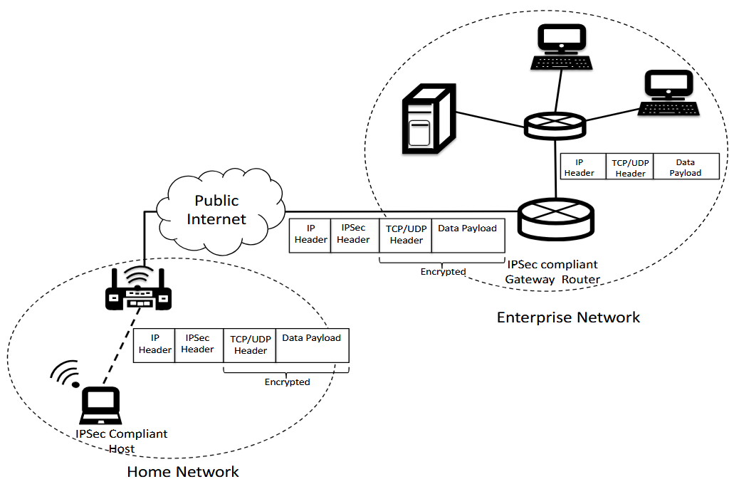
The figure illustrates a VPN implementation using IPSec. An employee is working in a home network; the client device (VPN client) encapsulates outgoing IPv4 datagrams into an IPSec frame and encrypts the IPv4 payload, which contains TCP or UDP segments or control messages. The organisation’s gateway identifies the incoming IPSec datagram, decrypts it, and extracts the IPv4 datagram before forwarding it to the destination server. The gateway also encrypts the server’s responses. IPSec provides data integrity, origin authentication, and replay protection during data transmission.
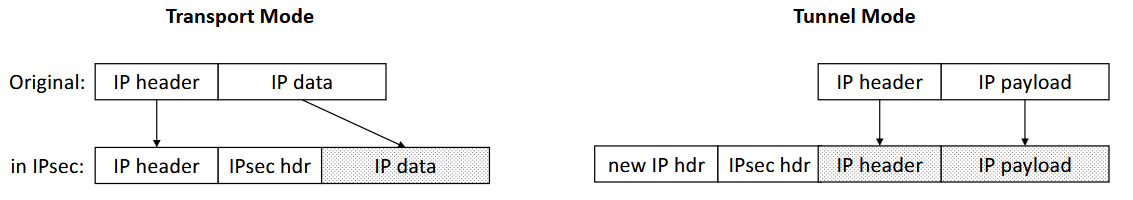
IPSec supports two modes of operation: tunnel and transport. These are compared side by side in the following figure. Transport mode protects the IP payload but not the IP headers (as in the previous figure). Tunnel mode creates new IP headers and protects the original ones. This is useful when the edge devices (routers/gateways) of two networks are IPSec-capable. In that case, other servers and hosts do not need to handle IPSec. The edge devices encapsulate each transmitted IP packet, including headers, and only the IP addresses of the edge devices are visible outside the two networks.
When a large number of endpoints use IPSec, manual distribution of IPSec keys becomes challenging. RFC 7296 defines the IKEv2 protocol, which performs an authenticated handshake and key establishment for IPSec at the application layer, similar to TLS.
NAT: Due to the scarcity of IPv4 addresses, NAT was developed to enable the use of private IP addresses by mapping them to a single public address. For outgoing traffic, the NAT device replaces the internal address with its own public address. NAT also provides indirect security benefits:
- The real IP addresses of internal network devices are not visible externally.
- External traffic is directed to the NAT device rather than directly to internal devices.
In addition, NAT devices such as home routers block direct incoming connections to the internal network by default. However, protection is weakened if exceptions are introduced, for example through port forwarding or via UPnP.
Link layer security
This subsection discusses link-layer security, mainly focusing on its logical aspects. The physical layer is discussed in more detail in the next module
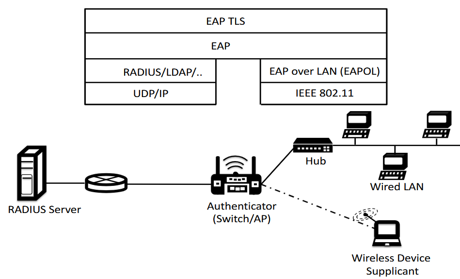
Port-based network access control (IEEE 802.1X) (advanced)
IEEE 802.1X provides port-based authentication for both wired and wireless networks. Before a device is allowed to access the network, it must authenticate itself via a switch or access point.
The operation is based on three parties: the client device, the network access point (switch or access point), and a separate authentication server (shown as a RADIUS server in the figure). The client uses the EAP protocol, through which authentication is relayed to the authentication server via the access point. The figure also shows the position of EAP in the protocol stack.
When a new device connects to the network, its port (at the access point) is placed in a restricted state where only authentication-related traffic is allowed and all other traffic is blocked. When authentication succeeds, the port is opened for normal traffic. When the connection ends, the port is returned to the restricted state. In this way, 802.1X ensures that only identified and authorised devices can access the network, significantly improving its security.
Link-layer security in wide area networks (advanced)
IEEE 802.1X is particularly suited to local area networks, whereas in wide area networks (WAN) similar functions are handled by protocols such as PPPoE and HDLC. These allow users to establish a connection to the internet via a service provider, and PPPoE in particular is very widely used.
The central objective is to ensure that only authorised users can access the network. For this reason, service providers typically require user authentication before a connection is established. Within PPP, various authentication protocols are used for this purpose, such as PAP, CHAP, and EAP-based solutions.
Of these, PAP is the weakest from a security perspective, as it transmits authentication information essentially unprotected. CHAP improves the situation by using a challenge–response mechanism, but it is not without problems either: stored session data may enable, for example, brute-force attacks if the credentials are weak.
Overall, at the link layer of wide area networks, the need for strong authentication methods is emphasised in order to reliably restrict network access and prevent unauthorised users from gaining entry.
Network segmentation (advanced)
MAC and ARP spoofing demonstrate how vulnerable network-layer protection can be. For this reason, networks are divided into smaller, separate entities – this is known as network segmentation. In critical environments, segmentation is often implemented physically, but for cost reasons, virtual segmentation is more common. VLAN networks are the practical standard here: they allow, for example, internal servers and guest networks to be separated logically, even if they use the same physical infrastructure.
Segmentation forces traffic to pass through routers, where it can be managed and restricted. This reduces the impact of attacks, as they cannot spread freely across the entire network. It is also important to note that segmentation does not require VPN solutions: if the segments are within the same local network, a router can connect them in a controlled manner. At best, this is complemented by firewall rules that direct and restrict traffic between networks.
VLAN hopping attacks allow access from one VLAN network to others, enabling an attacker to bypass segmentation restrictions and exploit protected resources. This undermines the basic idea of VLAN segmentation, namely isolating networks from each other. There are two main types of attack: switch spoofing and double tagging.
In switch spoofing, the attacker impersonates a switch and exploits protocols such as IEEE 802.1Q or the Dynamic Trunking Protocol to obtain a trunk connection. This allows the attacker to inspect traffic from multiple VLAN networks. The risk can be reduced by statically configuring port roles and disabling automatic trunk negotiation.
In double tagging, the attacker adds two VLAN tags to a frame. The first VLAN processes the outer tag and forwards the frame, after which the inner tag directs it to another VLAN network. In practice, the attack works only in one direction, but it still enables traffic monitoring and misuse.
The limitation of approximately 4096 VLAN networks is quickly reached, especially in highly virtualised environments. This issue is addressed by VXLAN, which uses encapsulation and moves segmentation to the network layer. This makes it possible to create up to millions of separate networks and to interconnect them flexibly, including with VLAN structures.
VXLAN, like VLAN, focuses on network segmentation and does not itself provide security features such as confidentiality or integrity. However, it introduces a new risk: because VXLAN traffic can traverse large networks such as the internet, attackers may attempt to inject falsified data into packets.
For this reason, traffic control and filtering are emphasised in VXLAN environments. In particular, at network edges it must be ensured that only trusted and correctly addressed VXLAN packets are allowed into the network, so that the risk of misuse remains under control.
Wireless security (advanced)
Wireless local area networks are exposed to security risks because the transmission medium is open and allows easy eavesdropping. Early protection, WEP, proved to be seriously vulnerable, and it was further developed into the WPA solution, which introduced, among other things, the pre-shared key, PSK.
The Wi-Fi Alliance standardised the WPA2 update in 2004. WPA2 is based on more powerful hardware than its predecessors and supports stronger encryption by using the AES algorithm in CCMP mode. This significantly improves both confidentiality and integrity protection. In addition, WPA2 utilises an improved four-way handshake to establish session keys. Although vulnerabilities have been identified in individual implementations, the structure of the handshake protocol itself is still considered secure.
In 2018, the WPA3 standard was approved, and its adoption is gradual. WPA3 addresses the shortcomings of earlier standards, particularly with regard to confidentiality. The pre-shared key is replaced with a new key exchange mechanism, SAE, which is based on strong key exchange and effectively prevents dictionary attacks. WPA3-Personal uses 128-bit encryption, while WPA3-Enterprise supports 192-bit encryption for higher-security environments.
It has been assumed above that a shared secret exists between WLAN users and access points, on the basis of which session keys can be established. In enterprise networks, access control is typically implemented using strong authentication, for example by using the IEEE 802.1X standard (i.e. the port-based authentication discussed earlier). In such cases, users often have personal client certificates, which provide significantly better protection than password-based solutions.
In open networks (for example at airports and in cafés), pre-shared keys or certificates cannot usually be used. In such cases, it is important to distinguish between protecting data transmission and restricting access to the network. Without encryption, communication remains unprotected. This issue is addressed by OWE, in which the client and access point establish an encrypted connection without a separately pre-shared secret. OWE is based on Diffie–Hellman key exchange and provides protection against passive eavesdropping even in open networks.